Quick Reference
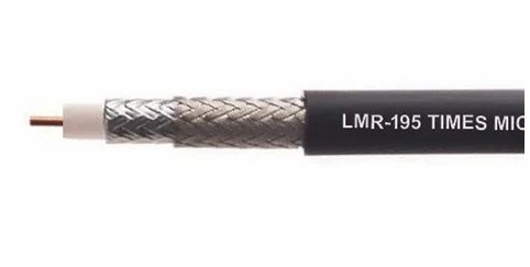
LMR195 Times Coaxial Cable
50 Ohm • DC – 6 GHz
LMR-195 is a Times Microwave 50-ohm flexible coaxial cable with a 0.195" outer diameter and very low loss compared to RG-58. Its aluminized tape plus tinned copper braid shield provides excellent 40 dB shielding, making it suitable for runs from 10 to 50 feet in WiFi, cellular, and two-way radio installations.
LMR195 Times Attenuation
Signal loss in dB per 100 ft at standard RF frequencies.
| Frequency | Loss / 100 ft | Loss / ft | 6 ft | 25 ft | 50 ft | 100 ft |
|---|---|---|---|---|---|---|
| 100 MHz | 3.3 dB | 0.033 dB | 0.2 dB | 0.83 dB | 1.65 dB | 3.3 dB |
| 450 MHz | 7.1 dB | 0.071 dB | 0.43 dB | 1.78 dB | 3.55 dB | 7.1 dB |
| 900 MHz | 10.2 dB | 0.102 dB | 0.61 dB | 2.55 dB | 5.1 dB | 10.2 dB |
| 1.8 GHz | 14.9 dB | 0.149 dB | 0.89 dB | 3.72 dB | 7.45 dB | 14.9 dB |
| 2.4 GHz | 17.3 dB | 0.173 dB | 1.04 dB | 4.33 dB | 8.65 dB | 17.3 dB |
| 5.8 GHz | 28.9 dB | 0.289 dB | 1.73 dB | 7.23 dB | 14.45 dB | 28.9 dB |
LMR195 Times Power Handling
Approximate maximum continuous power (CW) at 25°C ambient.
| Frequency | Max Power (W) |
|---|---|
| 100 MHz | 100 W |
| 450 MHz | 45 W |
| 900 MHz | 30 W |
| 1.8 GHz | 20 W |
| 2.4 GHz | 17 W |
| 5.8 GHz | 9 W |
Construction & Materials
Center Conductor
Bare copper clad steel, 1.12mm
The center conductor carries the RF signal. Material and diameter affect DC resistance, skin effect losses, and overall attenuation.
Dielectric
Foamed PE
The dielectric insulator separates the center conductor from the shield. PTFE dielectrics offer superior temperature stability and lower loss versus polyethylene.
Shield
Aluminum foil + tinned copper braid
The outer conductor provides the return path and shields the signal from external interference. More braid coverage means better EMI rejection.
Jacket
PE
The outer jacket protects the cable from physical damage, UV, chemicals, and moisture. PTFE and FEP jackets handle higher temperatures than PVC.
Velocity Factor
83% (c)
How fast the signal travels relative to the speed of light in vacuum. Higher velocity factor means shorter electrical wavelength per foot — important for phased array and delay-matched applications.
Max Voltage
600 VRMS
The maximum continuous operating voltage. Exceeding this can cause dielectric breakdown. Relevant for high-power transmitters and pulse applications.
Available LMR195 Times Assemblies
Choose a connector combination to see pricing and order. All assemblies are hand-built and ship free within the USA.
SMA MALE to SMA MALE
From $11.99
SMA FEMALE to SMA MALE
From $11.99
RP-SMA MALE to SMA MALE
From $11.99
RP-SMA FEMALE to SMA MALE
From $11.99
N MALE to SMA MALE
From $12.49
N FEMALE to SMA MALE
From $12.49
BNC MALE to SMA MALE
From $12.99
MCX MALE to SMA MALE
From $11.99
RP-TNC MALE to SMA MALE
From $11.99
SMA MALE to TNC MALE
From $11.99
F MALE to SMA MALE
From $12.99
F FEMALE to SMA MALE
From $12.99
FME MALE to SMA MALE
From $12.99
FME FEMALE to SMA MALE
From $12.99
PL259 UHF Male to SMA MALE
From $13.99
SMA MALE to SO239 UHF Female
From $13.99
BNC FEMALE to SMA MALE
From $12.99
SMA MALE to TNC FEMALE
From $11.99
153 more configurations available on the LMR195 Times page.
Frequently Asked Questions
What is the impedance of LMR195 Times?
LMR195 Times is a 50 Ohm coaxial cable. All standard RF systems (antennas, transceivers, test equipment) use 50-ohm impedance, so LMR195 Times connects directly without any matching network.
What frequency range does LMR195 Times support?
LMR195 Times is rated DC – 6 GHz. At higher frequencies, the attenuation per foot increases, so actual usable range depends on acceptable signal loss for your application.
How much signal loss does LMR195 Times have?
LMR195 Times has 3.3 dB of attenuation per 100 ft at 100 MHz, rising to 28.9 dB per 100 ft at 5.8 GHz. Use the attenuation table above to calculate loss for any specific length and frequency.
Are CoaxRF LMR195 Times cable assemblies made in the USA?
Yes. Every LMR195 Times assembly is hand-terminated and continuity tested at our US facility. We build each cable to order — nothing is pre-made or drop-shipped from overseas.
Can I order a custom length of LMR195 Times?
Yes. In addition to our standard lengths (1, 6, 25, 50, 100 ft and longer), we accept custom-length orders through the Cable Builder. Custom assemblies ship within 1–2 business days.